


Analog Input
The drive is fitted with differential inputs for analog torque, velocity, or position control. The standard drive offers one analog input on X21, dual axis drives and drives with built-in option IO or DX offer a second analog input on X22.
|
|
Maximum distance for unshielded I/O lines is 3 m inside the cabinet. If the I/O cable leaves the cabinet, it must be EMC shielded. |

Technical characteristics
- Differential input voltage range: ± 10 V
- Maximum input voltage referring to I/O Return: -12.5, +16.0 V
- Resolution: 16 Bit and fully monotonic
- Firmware update rate: 16 kHz
- Unadjusted offset: < 50 mV
- Offset drift typ: 250 µV / ° C
- Gain or slope tolerance: +/- 3%
- Nonlinearity: < 0.1% of full scale or 12.5 mV
- Common Mode Rejection Ratio: > 30 dB at 60 Hz
- Input impedance: > 13k Ωs
- Signal to noise ratio referred to full scale:
- AIN.CUTOFF = 3000 Hz: 14 bit
- AIN.CUTOFF = 800 Hz: 16 bit
Analog Input Wiring Diagram
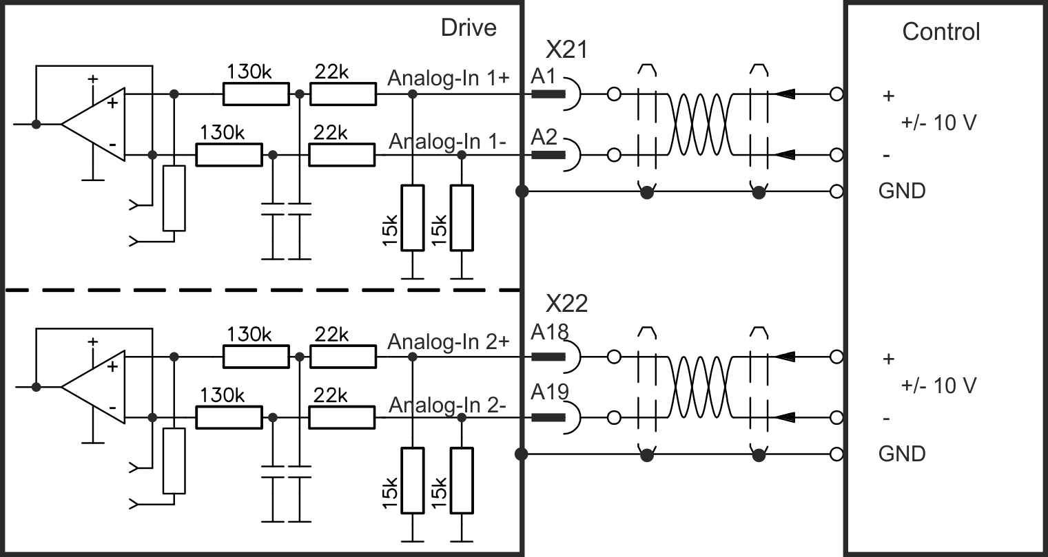
Application examples for set point input Analog-In:
- reduced-sensitivity input for setting-up/jog operation
- pre-control/override
Defining the direction of rotation
Standard setting: clockwise rotation of the motor shaft (looking at the shaft end) affected by positive voltage between terminal (+ ) and terminal ( - )
To reverse the direction of rotation, swap the connections to terminals +/- or change parameter AXIS#.DIR in WorkBench.